- 1. What is Bulk Molding Compound (BMC)?
- 2. Why BMC Gets Its Own Chapter
- 3. What Products Come Out of BMC Molds?
- 4. Why Choose BMC Over a Tough Thermoplastic?
- 5. How BMC Is Processed?
- 6. Structural Components of BMC Molds
- 7. Processing Parameters: How the Mold and Press Work Together
- 8. Maintenance of BMC Molds – Protect Your Investment
- 9. Conclusion
A thermoset composite mold,sometimes called a thermoset tool,is designed for materials that cure irreversibly under heat and pressure, including BMC/DMC, SMC, phenolic resins, and epoxy resins.Unlike thermoplastic molds, they work more like a heated chemical reactor. In a cycle, it must heat the compound to its curing temperature, control the flow of abrasive fibrous materials, expel volatile gases, and finally demold a rigid and permanently cured part—all while ensuring the part itself is hard, has low shrinkage, and is difficult to demold.
Therefore, the requirements for molds are higher, the tolerance for error is smaller, and the engineering design must consider not only mechanical properties but also chemical properties.
As a mold manufacturer specializing in motor components and magnetic assemblies, we work across the thermoset spectrum. But when asked which material takes up the most time in mold engineering, bulk molding compounds (BMC) is the answer.In this article, we will delve into the full scope of BMC materials.

What is Bulk Molding Compound(BMC)?
Bulk molding compound (BMC) is a high-performance thermosetting composite material. It is made by mixing an unsaturated polyester resin, chopped glass fibers, mineral fillers, catalysts, and various additives into a bulk form.Under high temperature and pressure, it undergoes an irreversible chemical reaction to cure, thus endowing it with excellent properties suitable for harsh application environments.
Composition
- Resin matrix: Primarily unsaturated polyester resin; vinyl ester or phenolic resins are used for high-temperature or high-corrosion resistance.
- Reinforcement: Chopped glass fibers, usually 3–25 mm in length, with a content of 10–30%.
- Fillers: Inert mineral fillers like calcium carbonate to improve dimensional stability and reduce cost.
- Additives: Include initiators, mold release agents, thickeners, low-profile (anti-shrink) additives, and pigments.
Key Properties
- Dimensional stability: Very low shrinkage; coefficient of thermal expansion close to metals.
- Mechanical strength: Higher tensile, flexural, and impact strength than many thermoplastics; excellent creep resistance.
- Heat resistance: Heat deflection temperature typically 200–280 °C; phenolic-based BMC can retain >60% of its mechanical properties at 300 °C.
- Electrical performance: High dielectric strength, excellent arc resistance, and adjustable flame retardancy and tracking resistance.
- Chemical resistance: Resists water, oils, aliphatic hydrocarbons, and many other chemicals.
- Design freedom: Good flowability allows complex shapes and precise details; paintable and electroplatable.
Why BMC Gets Its Own Chapter?
Among thermoset composites, BMC occupies a unique position, making them exceptionally difficult to mold,but also exceptionally valuable once successfully molded. BMC stands out due to 3 main characteristics.
- BMC is a ready‑to‑use compound
Unlike liquid resins that require mixing and degassing on a press, it arrives at the molding shop as a dough-like pre-impregnated material—resin, glass fiber, fillers, and catalysts are all mixed together. It handles like stiff clay,but it flows like thin honey under pressure and heating.This seemingly simple combination places extremely high demands on the mold: the mold must be able to contain the semi-solid material, guide it to every corner of the cavity, expel volatile substances, and finally eject the fully cured, rigid part.
- BMC has extremely low shrinkage
The shrinkage typically between 0.2% and 0.8%, sometimes even close to zero. This is a significant advantage for precision. However, it also means that once cured, the part will firmly grip the core, strong enough to break ejector pins or cause reinforcing ribs to crack. Thermoplastic parts will almost detach from the mold core after shrinking by a few percentage points. BMC parts, on the other hand, require careful ejection.
- BMC can be formulated with magnetic fillers, thus becoming a moldable magnetic material
For example, it can be mixed with ferrite or rare-earth powders. This dual nature of structure and magnetism makes BMC the cornerstone of plastic magnet manufacturing.Few other thermoset materials can fulfill both roles simultaneously.
Therefore, a good BMC mold maker needs a thorough understanding of this material before drawing any CAD lines. Everything in this guide is based on the properties of this material.
What Products Come Out of BMC Molds?
BMC parts are ubiquitous, hidden inside various components whose plastic parts generally shouldn’t be soft. Common applications include:


- Electrical insulation components: terminals, arc extinguishers, switch cabinet housings—these parts must withstand arcing and leakage without performance degradation.
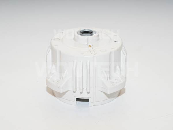
- Motor stators and motor assemblies: BMC is directly injection molded or compression molded onto the stator core to form an integrated, insulated housing.
- Plastic‑bonded magnets: Rotor rings, sensor magnets, and magnetic encoder wheels are molded from BMC filled with magnetic powder.
- Automotive engine compartment parts: valve covers, thermostat housings, ignition assemblies, etc., these components are located near the high-temperature environment of the engine.
- Lighting and home appliance parts: headlight reflectors, oven handles, washing machine structural supports—all these applications require heat resistance and good surface finish.
Why Choose BMC Over a Tough Thermoplastic?
I’m often asked, “Why not just use glass fiber reinforced nylon for molding?” Good question. Here’s a direct comparison:
- Heat Resistance
Nylon softens, while BMC doesn’t. Nylon parts creep, deform, and even fail under continuous use temperatures approaching 200°C, and with intermittent exposure to even higher temperatures. BMC parts, on the other hand, maintain their shape until they char.
- Dimensional Stability
BMC has virtually zero mold shrinkage, meaning parts are removed from the mold very close to their printed dimensions and maintain those dimensions. Nylon absorbs moisture, and ambient humidity alone can cause dimensional changes exceeding one percent. This is a fatal flaw for motor stators requiring concentricity within a few percent of millimeters.
- Electrical Insulation and Flame Retardancy
BMC has inherent arc-tracking resistance and meets UL 94 V-0 standards without the need for halogen additives. Thermoplastics require more additives, which can affect their mechanical properties.
- Chemical Resistance
Oil, fuel, transmission fluid, weak acids—BMC can handle it all. Nylon, on the other hand, may swell or degrade.
- Advantages in Processing Complex Shapes
Because BMC thins rapidly when heated within the cavity, complex geometries can be filled and metal inserts encapsulated in a single step, eliminating assembly steps.
Any disadvantages of BMC?
Compared to resilient thermoplastics, BMC is more rigid and brittle—clip-on or movable hinges cannot be used. Processing cycles are longer because the material must be chemically cured, not just cooled.
Furthermore, molds must be more robust: BMC molds require a larger initial investment and have higher maintenance costs than equivalent thermoplastic molds. However, its long-term value for the right project is undeniable.
How BMC Is Processed?
Before delving into the mold structure, we need to understand how BMC enters the mold cavity from a paste-like state. There are two main pathways, each with different impacts on mold design.
Injection Molding
- Using a specialized BMC injection machine, the material is plasticized in a barrel at 135–185 °C and injected under high pressure (80–160 MPa) into a closed, heated mold for rapid curing.
- Injection molding is the preferred method for high-volume production, thin-walled parts, and parts requiring high-precision injection molding consistency. The vast majority of our motor stator encapsulation work falls into this category.
Compression Molding
- Block BMC material is placed directly into a heated metal mold, then pressurized and cured at high temperature.Because the material doesn’t need to pass through narrow nozzles and runner systems, fiber breakage is lower.
- Compression molding is suitable for larger, thicker parts because maintaining fiber length helps increase strength. Some large magnetic rotors are manufactured using compression molding for this reason.
For mold designers, compression tooling requires careful consideration of shear edges (to control flash) and loading positions (to ensure complete filling and no air bubbles). Injection molding molds focus more on runners, gates, and venting systems. However, fundamental elements such as thermal uniformity, venting, steel selection, and ejection apply to both molding processes.
Structural Components of BMC Molds
BMC molds differ from standard molds. They integrate a thermal reactor, fluid management system, gas venting network, and precision mechanical components. Let’s examine each subsystem in the order of actual workshop operation.
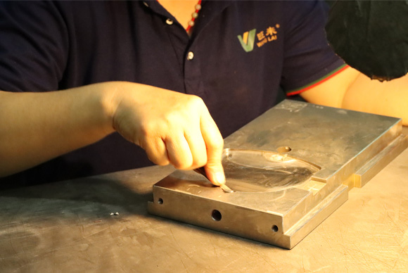
1 – Cavities and Cores: Precise Geometry Control
The cavity is the recessed female mold; the core is the male mold used to form internal features. For BMC molds, the steel cutting dimensions do not match those on the part drawings.
- Shrinkage Compensation
BMC has a small but present shrinkage rate. Therefore, the mold dimensions must be slightly larger—typically 0.2% to 0.8%, depending on the BMC grade.The challenges are:
1)The shrinkage rate is not uniform across the entire part.
2)Thicker bosses have different shrinkage rates than thinner reinforcing ribs.
3)The material near the gate solidifies faster, and its shrinkage rate may differ from that at the end of the runner.
- Wall Thickness Uniformity
BMC parts should be designed with consistent wall thickness. Sudden changes in wall thickness can lead to uneven curing, resulting in residual stress and post-mold warping.
- Draft Angles
Due to the extremely low shrinkage of BMC, cured parts can firmly hold the core. We recommend a draft angle of at least 1° to 3° for all surfaces parallel to the mold opening. Deep cores and textured surfaces require larger draft angles; insufficient draft angle is the most common cause of demolding defects.
2 – Gating System: How Material Enters the Cavity
In injection molds, material enters the mold through the barrel, the runner, and finally the cavity. The design of this path affects everything from fiber length to part surface finish.
- Gate Type
Tiny needle-like gates can shear glass fibers and may cause premature curing due to frictional heat. For BMC materials, we prefer side gates, fan gates, or lug gates, as these larger openings allow material to enter the cavity with less damage.
Self-ejecting designs can separate the runner from the part when the mold opens, saving significant finishing work during production.
- Hot Runner Technology
In traditional cold runner systems, the BMC material in the runner cures along with the part. The cured runner becomes waste,and because BMC is a thermosetting material, it cannot be re-grinded and reused.Hot runner systems maintain the runner temperature below the curing initiation temperature, typically 80-100°C.The material inside the mold remains fluid, with only the portion entering the cavity solidifying.During the next injection, fresh BMC pushes the still-flowable material from the runner into the cavity.
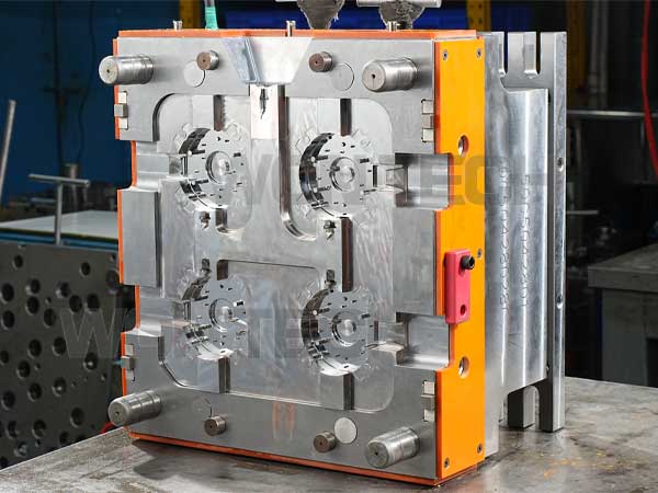
For multi-cavity molds, hot runners can reduce material waste by 20-40% and shorten production cycles.
- Flow Simulation
Modern mold flow analysis can simulate the behavior of thermosetting materials, including curing kinetics and fiber orientation. Before cutting steel, we perform fill simulations to identify potential cavitation, weld line locations, and areas of excessive fiber orientation. The cost of simulation is far lower than the cost of fixing casting errors in hardened molds.
3 – Thermal Control: The Key to Stable Curing
If I had to choose one system that has the greatest impact on the success or failure of BMC molds, it would be the thermal system. Uneven temperature leads to uneven curing, resulting in inconsistent dimensions, residual stress, blistering, and poor surface quality.
- Temperature Requirements
BMC processing typically requires mold temperatures between 135°C and 170°C, with cavity surface temperature uniformity controlled within ±5°C.I have measured some poorly designed molds with temperature fluctuations exceeding 15°C; these molds consistently exhibited unstable operation.
- Heating Methods
Electric heating rods are simple to use and start quickly, but improper placement can easily create localized overheating.
Oil-based thermal fluid circulation heating provides more uniform heating and more precise zone control, but requires an external temperature control unit and a more complex piping system.
For high-volume production molds, we typically prefer oil-based circulation heating with multiple independently controlled zones: the gate area, thick-walled areas, and thin-walled areas, each adjusted according to its specific thermal requirements.
- Heater Location
The cylindrical heater or oil channel should be located approximately 40–80 mm from the cavity surface.Its density should be higher near the mold edge, as heat loss is greatest there. In the central area, the density should be lower, as the thermal quality is better and insulation is superior.
4 – Venting: Expelling Gases
The BMC curing reaction produces volatile byproducts—primarily styrene vapor and water. The mold cavity is also initially filled with air. If these gases lack venting channels, they become trapped and compressed, leading to porosity, bubbles, burn marks, or incomplete filling. Venting is one of the most easily underestimated elements in BMC mold design.
- Ventilation Channel Dimensions
At the parting line and final filling area, we typically machine vents 0.02–0.05 mm deep and 3–5 mm wide.These values are carefully chosen: deep enough for gas passage, yet shallow enough to prevent low-viscosity BMC melt from splashing into the vents and causing blockages.
For parts requiring high porosity, we connect these venting channels to a vacuum pump to actively extract gas during the filling phase.
- Location
Vents must be located at the final filling point, where the flow front finally converges. We determine these points through short-shot tests and compare the results with our mold flow simulations. Placing vents in the middle of the runner only expels material without affecting downstream cavitation.
- Maintenance
After hundreds of cycles, the venting channels become clogged with resin residue and worn filler. The effectiveness of the vents gradually decreases, and the scrap rate increases accordingly. Regular cleaning of the vents should be an essential part of mold maintenance.
5 – Ejection: Complete Removal of Parts
As I mentioned, BMC ejection is challenging due to its low shrinkage, high rigidity after curing, and tendency for the material to adhere to steel. Therefore, the ejection system must be robust and durable.
- Dual-sided Ejection
Since it’s impossible to accurately predict which side of the mold the part will adhere to, we typically design ejection assemblies on both the moving and stationary sides. This ensures smooth demolding regardless of which side the part adheres to.
- Ejector Pin Position
Ejector pins should abut against non-visible surfaces and have sufficient cross-sectional area to avoid puncturing the cured part. For complex geometries with deep ribs, tilting ejector pins or sliding mechanisms may be necessary for demolding undercuts without stressing the rigid BMC.
- Demolding Surface Coating
The right surface finishing, such as hard chrome, nitriding, or PVD coatings, not only prevent wear but also significantly reduce adhesion between the cured BMC and the mold surface. Many ejection problems are not solved by increasing the number of pins but by improving surface chemistry.
6 – Tool Steel Selection and Surface Finishing
BMC molds operate in extremely harsh environments: continuous high temperatures up to 170°C, the abrasiveness of glass fiber, and the slight corrosive chemical exposure with each cycle. The steel you choose determines the mold’s lifespan.
- Steel Grade
For prototyping or low-volume production, pre-hardened steels such as P20 or 718H (hardness 32-36 HRC) are sufficient with appropriate surface finishing.For production runs in the hundreds of thousands of cycles, which is common in automotive and electrical component manufacturin,we recommend hot-work die steels such as H13 (DIN 1.2344), with a hardness of 48-52 HRC. H13 resists thermal fatigue cracking, which can ultimately lead to the failure of other steels.
- Surface Finishing
Hard chrome plating is the traditional benchmark. To extend service life, nitriding or PVD coatings (CrN, TiN, or newer multilayer coatings) offer superior surface hardness and chemical inertness.These treatments can save significant costs by extending mold refurbishment intervals.
Processing Parameters: How the Mold and Press Work Together
BMC molds differ from standard molds. They integrate a thermal reactor, fluid management system, gas venting network, and precision mechanical components. Let’s examine each subsystem in the order of actual workshop operation.
- Mold Temperature
The operating temperature range is 140-170°C.
Thinner parts can use higher temperatures to accelerate curing; thicker parts require lower temperatures to avoid scorching the surface before the exothermic curing reaction occurs and cross-links internally.
- Injection Pressure and Speed
For injection molding, injection pressures are 80-160 MPa, and filling speeds are 1.8-3.5 m/min.
Faster filling speeds generally improve surface finish and shorten overall cycle time, but may increase fiber orientation and make venting more difficult. We determine the process window during mold trials by varying the filling speed and observing part quality.
- Clamping Force
The press must provide sufficient clamping force to resist the injection pressure over the projected area of the part.For compression molding of BMC, the standard unit pressure is 30-50 MPa over the projected area of the part.
- Curing Time
The curing time for injection-molded BMC is approximately 10-20 seconds per millimeter of wall thickness.
Compression molding cycles are longer, ranging from 60 to 300 seconds, depending on the part’s quality and geometry.
- Screw Speed and Back Pressure (Injection Molding)
To minimize glass fiber breakage during plasticization, a low screw speed (20-50 rpm) and minimal back pressure (1.4-2.0 MPa) should be maintained. The screw itself should have a low compression ratio specifically designed for thermosetting compounds.
Maintenance of BMC Molds – Protect Your Investment
BMC molds are a capital asset whose economic value depends on their maintenance over a service life of 10 years or more.
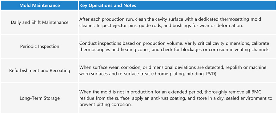
| Mold Maintenance | Key Operations and Notes |
|---|---|
| Daily and Shift Maintenance | After each production run, clean the cavity surface with a dedicated thermosetting mold cleaner. Inspect ejector pins, guide rods, and bushings for wear or deformation. |
| Periodic Inspection | Conduct inspections based on production volume. Verify critical cavity dimensions, calibrate thermocouples and heating zones, and check for blockages or corrosion in venting channels. |
| Refurbishment and Recoating | When surface wear, corrosion, or dimensional deviations are detected, repolish or machine worn surfaces and re-surface treat (chrome plating, nitriding, PVD). |
| Long-Term Storage | When the mold is not in production for an extended period, thoroughly remove all BMC residue from the surface, apply an anti-rust coating, and store in a dry, sealed environment to prevent pitting corrosion. |
Conclusion
Thermosetting materials—BMC molds are more than just cavities; they integrate heat engines, venting systems, and precision fixtures.Treating them like ordinary thermoplastic molds will leave you perpetually dealing with flash, bubbles, and cracks.Respect the material’s characteristics: low shrinkage, volatile gases, and wear resistance,and the mold can run reliably for a decade.
This article covers the principles we follow when problems arise: maintaining uniform heating, ensuring unobstructed gas venting, and never cutting corners on steel and surface treatments. I wrote this guide because these are precisely the things I frequently need to explain on the shop floor or when speaking with customers. If it helps you avoid the repeated trials we’ve experienced, then it’s worthwhile.
If you are machining thermosetting parts and would like to discuss mold design methods, or if you have any questions not covered in this article, please feel free to contact us! We’d love to discuss them with you!
Author’s Note
“I have spent most of my career working with molds that must form parts in a single shot—there is no chance for remelting, nor is there room for a second attempt. This is the world of thermosetting materials.
In this field, the material I receive the most inquiries about is bulk molding compound (BMC). This guide is exactly the kind of resource I wish someone had handed me when I first entered the industry. Whether you are sourcing molds, designing parts, or simply trying to understand exactly what you’re paying for, this guide assumes you have a curiosity about BMC mold manufacturing. It starts with the basics and gradually delves into the engineering details that ensure smooth production. Motor stators and magnetic components are frequently mentioned throughout, as they are the core of our shop’s business, but the principles discussed here apply to any BMC mold, regardless of size.”
Discuss Your Tooling Requirements
We deliver mold design, plastic raw material compounding, and molding production as a turnkey service.
- Integrated supply chain
- Experts in all types of electric motor molds
- Plastic‑bonded magnet solutions
- Engineered from production experience
Wontech is trusted by industry leaders
- 20+ years
- ISO 9001
- 40+ patents
- No.2, South Huatai East Road, Caosan PioneerPark,ZhongShan,Guangdong,China
- +86 13326981626
- ocean.h@wanglai.cn
CAPABILITIES
COMPANY


Copyright ©2026 Wontech | Powered by Wontech.All Rights Reserved.