Precision CNC Machining Service
Precision machining and post-processing of molds are the final forging of superior quality. This is not only about achieving the required dimensions, but also about realizing the ultimate performance, appearance, and reliability. We ensure the micron-level precision and perfect surface of our molds through high-precision CNC and EDM; and through systematic post-processing (such as spraying, printing, and assembly), we endow parts with functionality and commercial value, transforming stable mold capabilities into high-quality products that can be applied directly.
Precision CNC Machining Capabilities
Our dedicated CNC machining department combines advanced 3-axis and 4-axis machining centers with specialized milling and turning capabilities to deliver precision components and mold inserts with tight tolerances. By leveraging strategic fixturing and process optimization, we achieve complex geometries typically requiring 5-axis equipment through smart engineering solutions.
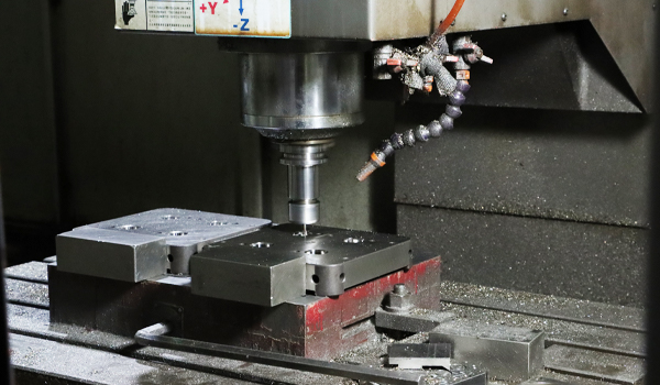
CNC Milling
CNC milling is the core process for realizing complex three-dimensional cavities in molds. Through multi-axis linkage and high-speed machining technology, we can precisely transform digital designs into mold cores, inserts, and slides with superior geometric accuracy and surface quality. This not only ensures that the shape and dimensions of the final injection-molded parts perfectly match the design intent but also lays a solid foundation for subsequent polishing and assembly, representing the first step towards efficient mold manufacturing and excellent product reproducibility.
Professional Capabilities
- Positioning Accuracy:±0.005mm
- Micro-feature Machining (Minimum Groove Width 0.2mm)
- Deep Cavity Machining(Depth-to-Diameter Ratio 15:1)
- Precision Electrode Manufacturing (for EDM Process)
- Precision Machining of Mold Core and Cavities
Process Advantages
- Dedicated fixture design for multi-faceted machining of complex parts
- High-Speed Machining (HSM) technology reduces thermal deformation
- Dedicated cutting parameter library optimized for different mold steels
- Collaboration with EDM processes to solve complex geometries
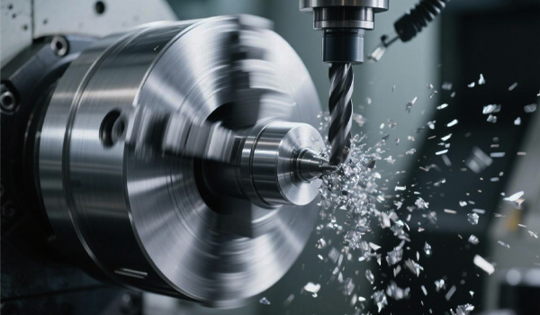
CNC Turning
CNC turning centers are pivotal for machining high-precision rotational mold parts and inserts. They efficiently handle turning operations for cylinders, bores, faces, and complex threads. Equipped with live tooling for milling and drilling, they enable complete machining in a single setup. This guarantees critical components like guide pins, sleeves, and inserts achieve exceptional dimensional accuracy, surface finish, and concentricity, providing reliable assurance for smooth mold operation and extended service life.
Machining Capabilities
- Precision shaft parts (motor shafts, guide pillars, etc.)
- Custom mold standard parts (guide bushings, ejector pins, etc.)
- Mass production of rotationally symmetric parts
- Mill-turn machining (some equipment supports Y-axis and C-axis function)
Special Processes
- Ultra-precision cutting (surface roughness Ra 0.4μm)
- Hard turning (HRC 45+materials)
- Micro-turing (fine shafts with diameters of 0.5mm and above)
- Precision thread machining (metric/imperial/special threads)
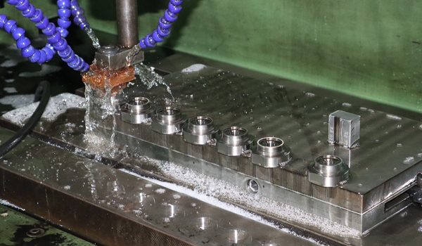
Precision CNC Machining
The superior performance of a mold is ultimately determined by the perfect collaboration of every precision part. We focus on the independent manufacturing and matching of key functional units such as guide pillars, slides, inserts, and hot runner nozzles.
Specialty Areas
- Precision Machining of Core Components for Motor Molds
- Machining of High-Hardness Parts in BMC Molds (HRC 50+)
- Precision Fitting Parts for Hot Runner Systems
- Precision Machining of Sliders and Core-Pulling Mechanisms
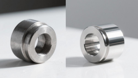
EDM
Using controlled electrical discharge machining to process extremely hard metals, complex details and fine surfaces that are impossible to achieve with traditional cutting tools can be obtained.
- Machining of cavities in high-hardness mold steel (HRC 50+)
- Micro-venting grooves and texture features
- Precision forming of irregular shapes
- Stress-free machining of difficult-to-machine materials
WEDM
It uses continuously moving filaments as electrodes to etch complex contours and fine morphologies in hardened steel with unparalleled precision and a fine surface finish.
- Non-contact cutting, no mechanical stress
- Suitable for ultrahard materials and precision dies
- Can machine complex 2D contours and 3D shapes
- Standard surface roughness Ra 0.8μm, optimizeable to Ra 0.2μm
Precision CNC Machining Capabilities
Our dedicated CNC machining department combines advanced 3-axis and 4-axis machining centers with specialized milling and turning capabilities to deliver precision components and mold inserts with tight tolerances. By leveraging strategic fixturing and process optimization, we achieve complex geometries typically requiring 5-axis equipment through smart engineering solutions.
CNC Milling
CNC milling is the core process for realizing complex three-dimensional cavities in molds. Through multi-axis linkage and high-speed machining technology, we can precisely transform digital designs into mold cores, inserts, and slides with superior geometric accuracy and surface quality. This not only ensures that the shape and dimensions of the final injection-molded parts perfectly match the design intent but also lays a solid foundation for subsequent polishing and assembly, representing the first step towards efficient mold manufacturing and excellent product reproducibility.
Professional Capabilities
- Positioning Accuracy:±0.005mm
- Micro-feature Machining (Minimum Groove Width 0.2mm)
- Deep Cavity Machining(Depth-to-Diameter Ratio 15:1)
- Precision Electrode Manufacturing (for EDM Process)
- Precision Machining of Mold Core and Cavities
Process Advantages
- Dedicated fixture design for multi-faceted machining of complex parts
- High-Speed Machining (HSM) technology reduces thermal deformation
- Dedicated cutting parameter library optimized for different mold steels
- Collaboration with EDM processes to solve complex geometries
CNC Turning
CNC turning centers are pivotal for machining high-precision rotational mold parts and inserts. They efficiently handle turning operations for cylinders, bores, faces, and complex threads. Equipped with live tooling for milling and drilling, they enable complete machining in a single setup. This guarantees critical components like guide pins, sleeves, and inserts achieve exceptional dimensional accuracy, surface finish, and concentricity, providing reliable assurance for smooth mold operation and extended service life.
Machining Capabilities
- Precision shaft parts (motor shafts, guide pillars, etc.)
- Custom mold standard parts (guide bushings, ejector pins, etc.)
- Mass production of rotationally symmetric parts
- Mill-turn machining (some equipment supports Y-axis and C-axis function)
Special Processes
- Ultra-precision cutting (surface roughness Ra 0.4μm)
- Hard turning (HRC 45+materials)
- Micro-turing (fine shafts with diameters of 0.5mm and above)
- Precision thread machining (metric/imperial/special threads)
Precision CNC Machining
The superior performance of a mold is ultimately determined by the perfect collaboration of every precision part. We focus on the independent manufacturing and matching of key functional units such as guide pillars, slides, inserts, and hot runner nozzles.
Specialty Areas
- Precision Machining of Core Components for Motor Molds
- Machining of High-Hardness Parts in BMC Molds (HRC 50+)
- Precision Fitting Parts for Hot Runner Systems
- Precision Machining of Sliders and Core-Pulling Mechanisms
EDM
Using controlled electrical discharge machining to process extremely hard metals, complex details and fine surfaces that are impossible to achieve with traditional cutting tools can be obtained.
- Machining of cavities in high-hardness mold steel (HRC 50+)
- Micro-venting grooves and texture features
- Precision forming of irregular shapes
- Stress-free machining of difficult-to-machine materials
WEDM
It uses continuously moving filaments as electrodes to etch complex contours and fine morphologies in hardened steel with unparalleled precision and a fine surface finish.
- Non-contact cutting, no mechanical stress
- Suitable for ultrahard materials and precision dies
- Can machine complex 2D contours and 3D shapes
- Standard surface roughness Ra 0.8μm, optimizeable to Ra 0.2μm
Our Differentiated Machining Services
Many clients have told us that their current suppliers often present numerous limitations during the customization process. Many innovative projects and startups are constrained by traditional production models—high minimum order quantities or limited material choices—which is precisely why we’ve developed differentiated services.We don’t just provide manufacturing services; we’re committed to being a reliable link in your supply chain. Whether you need small-batch pilot production to validate your design or seek performance breakthroughs through the processing of special materials, we will help you efficiently transform your ideas into reality with our focused process knowledge and customized solutions.
Flexible Production Solutions - Low-volume Parts Manufacturing
We focus on providing flexible production solutions that seamlessly connect your entire product development lifecycle. Whether it’s design verification, small-batch pilot production, or full-scale orders, we respond quickly and significantly reduce your mold investment, inventory pressure, and market risks through efficient processes and scheduling, helping you get to market quickly.
Material Flexibility - Metal and Engineering Plastics Machining
We offer a wide selection of materials, from aluminum alloys and stainless steel to engineering plastics and specialty composites. We can provide scientific material selection advice and customized process solutions (such as precision machining and injection molding) tailored to your performance requirements, cost budget, and post-processing needs, ensuring that parts achieve the optimal balance in strength, weather resistance, or special functions.
Why Partner With Us
- A True Turnkey Solution
- Experienced professional team
- Globally certified reliability
- Optimized supply chain for improved cost-effectivenes
- Forward-thinking innovative partnerships
- Focused and rapid response
Why Partner With Us
- A True Turnkey Solution
- Experienced professional team
- Globally certified reliability
- Optimized supply chain for improved cost-effectivenes
- Forward-thinking innovative partnerships
- Focused and rapid response
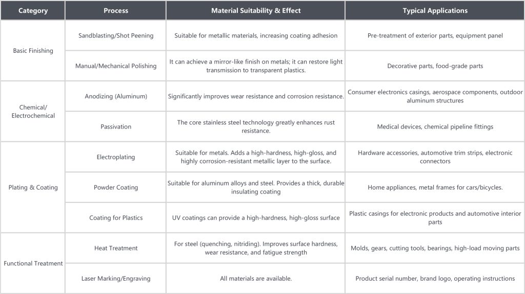
CNC Machining Surface Finishing Options
Professional surface finishing, as a crucial final step, not only significantly improves the wear resistance and corrosion resistance of parts, optimizes their mechanical and electrical properties, but also enhances the product’s aesthetics. We offer complete solutions from basic finishing to specialty coatings, ensuring that every part can be applied in its optimal form.
|
Category
|
Process
|
Material Suitability & Effect
|
Typical Applications
|
|---|---|---|---|
|
Basic Finishing
|
Sandblasting/Shot Peening
|
Suitable for metallic materials, increasing coating adhesion
|
Pre-treatment of exterior parts, equipment panel
|
|
Manual/Mechanical Polishing
|
It can achieve a mirror-like finish on metals; it can restore light transmission to transparent plastics.
|
Decorative parts, food-grade parts
|
|
|
Chemical/Electrochemical
|
Anodizing (Aluminum)
|
Significantly improves wear resistance and corrosion resistance.
|
Consumer electronics casings, aerospace components, outdoor aluminum structures
|
|
Passivation
|
The core stainless steel technology greatly enhances rust resistance.
|
Medical devices, chemical pipeline fittings
|
|
|
Plating & Coating
|
Electroplating
|
Suitable for metals. Adds a high-hardness, high-gloss, and highly corrosion-resistant metallic layer to the surface.
|
Hardware accessories, automotive trim strips, electronic connectors
|
|
Powder Coating
|
Suitable for aluminum alloys and steel. Provides a thick, durable insulating coating
|
Home appliances, metal frames for cars/bicycles.
|
|
|
Coating for Plastics
|
UV coatings can provide a high-hardness, high-gloss surface
|
Plastic casings for electronic products and automotive interior parts
|
|
|
Functional Treatment
|
Heat Treatment
|
For steel (quenching, nitriding). Improves surface hardness, wear resistance, and fatigue strength
|
Molds, gears, cutting tools, bearings, high-load moving parts
|
|
Laser Marking/Engraving
|
All materials are available.
|
Product serial number, brand logo, operating instructions
|
CNC Machining Surface Finishing Options
Professional surface finishing, as a crucial final step, not only significantly improves the wear resistance and corrosion resistance of parts, optimizes their mechanical and electrical properties, but also enhances the product’s aesthetics. We offer complete solutions from basic finishing to specialty coatings, ensuring that every part can be applied in its optimal form.
Client Inquiries

“Is our design feasible for CNC machining? What are the key design limitations and optimization suggestions?”
We offer free DFM analysis. Before providing a quote, we will review your 3D model based on the following principles and provide a written report that clearly identifies potential problems (such as excessively thin wall thickness or difficult-to-machine internal features) and offers optimization suggestions.
1.Material Selection and Machinability:
Basic Principles: The hardness, toughness, thermal conductivity, and tool wear of a material directly affect machining difficulty and cost. For example, aluminum alloys (such as 6061, 7075) are easy to machine and have long tool life; while stainless steel (such as 304, 316) or mold steel (such as P20, S7) require high-quality tools, have slow machining speeds, and significantly increase costs.
Key Recommendation: Review material selection with your engineers. Recommending standard grades that are easier to machine, while meeting functional requirements, can significantly reduce costs and shorten lead times.
2.Geometry and Key Constraints (More in-depth details beyond general fillet and wall thickness principles):
Deep Cavity/Deep Hole Machining: Machining where the depth is greater than 5 times the diameter is considered “deep cavity/deep hole” machining. This requires special extended tools and may involve “pecking drills” or high-pressure internal cooling to prevent tool runout, breakage, and poor chip removal. Machining time and costs increase non-linearly.
Thin-walled and high-ribbed parts: For aluminum alloys, the limit for stable machining of thin walls is approximately 0.5mm; for steel, it is approximately 1.0mm. Isolated, high, and thin ribs should be avoided in the design, as they will cause vibration and deformation during machining due to cutting forces. It is recommended to increase rigidity by adding reinforcing ribs or changing the direction of the ribs.
Internal right angles and corner clearing: CNC milling cutters cannot machine true internal right angles; all internal angles will have a fillet formed by the tool radius. If corner clearing is functionally required for the part, it must be completed subsequently through electrical discharge machining (EDM), which increases the number of processes and costs. Reasonable process fillets should be reserved in non-critical locations during the design.
3.Tolerances and surface finish:
Economic tolerances: For most CNC milling operations, ±0.05mm is an economical and reliable accuracy level. Pursuing higher tolerances (such as ±0.01mm) requires more precise machine tools, stricter temperature control, and more complex inspection procedures, which will drastically increase costs.
Surface treatment and substrate: If the parts require subsequent treatments such as anodizing or electroplating, the surface finish (Ra value) after processing must meet the requirements of the processing technology. For example, high-gloss mirror electroplating requires the substrate to reach a very high polishing level.
“How do you solve the tool accessibility problem for complex internal features and deep cavity structures?”
Complex internal features and deep cavity structures are indeed challenges for CNC machining. We adopt a multi-layered solution:
1. Dedicated Tooling Strategy:
Length-to-Diameter Ratio Optimization: Using high-rigidity, slender tools (maximum depth-to-diameter ratio 15:1), such as a Ø3mm tool for machining a 45mm depth.
Custom Tooling: Developing non-standard tools for specific projects, such as variable-diameter toolholders, eccentric tool heads, and miniature ball end mills.
Modular System: Employing heat-shrink or hydraulic toolholders to improve the rigidity of slender tools and reduce vibration.
Tooling Innovation:Using tools with internal cooling channels to optimize chip removal and cooling in deep cavities.
2. Innovative Process Methods:
Split-type Design: Complex internal cavities are broken down into 2-3 machinable components, precisely positioned and assembled to form a complete structure.
Electrical Discharge Machining (EDM) Collaboration:CNC machining of the basic shape, EDM processing of complex internal contours, leveraging the strengths of each.
Flip Machining Strategy: Designing dedicated flip fixtures for multi-face machining in a single setup, reducing datum conversion errors.
Tilt Machining:Utilizing the machine’s rotation function to adjust the workpiece angle for optimal tool entry path.
3. Simulation and Verification:
Comprehensive Collision Detection Before Machining:Pre-processing collision detection to identify tool interference in advance.
Virtual Machining Verification:Optimizing toolpaths to reduce idle travel and unnecessary reversals.
"How do you ensure the surface finish of CNC machined parts? What standards can you achieve?"
Surface Finish Capabilities and Standards:
Standard Machining: Ra 1.6-3.2μm (Suitable for non-surface, non-sealing surfaces)
Precision Machining: Ra 0.8-1.6μm (Suitable for general mating surfaces, medium-requirement appearance)
Ultra-Precision Machining: Ra 0.2-0.4μm (Suitable for sealing surfaces, mirror finish requirements, optical applications)
Mirror Polishing: Ra 0.025-0.05μm (Achieved through subsequent manual polishing, not directly through CNC machining)
Surface Quality Control System:
1. Process Parameter Optimization:
Cutting Parameters: High-speed machining (12,000-24,000 rpm) is used for precision machining. RPM), small depth of cut (0.05-0.1mm), appropriate feed rate
Tool Selection:Ball end mills are used for surface finishing; the tip radius is selected based on the minimum radius of curvature.Diamond inserts are used for flat surfaces; the tip radius is 0.2-0.4mm to optimize surface quality.Contour finishing is used to reduce tool lift-off and re-entry marks.Spindle balance level G2.5 to avoid resonant frequency areas.
2. Process Monitoring Measures:
Online surface roughness prediction based on cutting force and vibration sensor data.
First-piece surface quality verification using a portable roughness meter for on-site inspection.
Surface quality is sampled every 2 hours, trends are recorded, and parameters are adjusted promptly.
Tool wear monitoring; automatic tool replacement when surface roughness increases by 10%.
3. Post-processing Technology:
Deburring: Automated deburring machine or manual finishing for micro-burrs.
Surface Strengthening: Vibration polishing and shot peening to improve surface fatigue strength.
Chemical Treatment: Chemical polishing for specific materials.
Professional Polishing: Manual mirror polishing of mold cavities to achieve VDI 3400 #A1 level.
Industry Standard Comparison:
VDI 3400 Standard: #12 (Ra 0.4μm), #15 (Ra 0.25μm), #18 (Ra 0.14μm), #21 (Ra 0.08μm)
SPI Standard: A-1 (Mirror Finish), A-2 (High Gloss), B-1 (Standard Finish), C-1 (Textured Finish)
“Under what circumstances would you recommend using 4-axis or 5-axis machining? How do we determine if our parts require it?”
Choosing a multi-axis machine tool isn’t always because the parts “look” extremely complex, but rather based on several very practical technical reasons that bring you direct value. Simply put, we strongly recommend it primarily in the following three situations:
When you are looking for “one-time setup, all done”, and when a part has multiple faces that need to be machined, a five-axis machine tool can reduce repeated setups by rotating the worktable, greatly improving accuracy and efficiency.
When your parts involve complex curved surfaces or spatial geometry,For complex free-form surfaces used in aerospace and automotive molds, five-axis linkage can maintain the optimal cutting angle and obtain better surface quality.
When your design has “deep cavity sidewalls” or “slanted orifices”,multi-axis machine tools can use shorter tools to approach the sidewalls of deep cavity parts or angled holes and surfaces at a specific angle, thereby improving rigidity, reducing vibration, and avoiding tool interference.
“What causes vertical or horizontal lines on the surface of machined parts? How do you prevent them?”
These grooves are mainly caused by unwanted vibrations or unevenness during machining. We can quickly pinpoint the general direction of the problem based on the direction of the grooves:
If it’s a vertical groove (along the cutting direction): This is usually due to “vibration,” primarily caused by:
1.The tool or workpiece isn’t gripped properly: The tool is extended too far, wobbles slightly, or the part is slightly loose in the fixture.
2.The cut is too sharp or too blunt: The cutting parameters are unsuitable for the material, or the tool is worn and dull.
3.The machine tool is in poor condition: There are small gaps or wear in the machine tool’s lead screw, guide rails, etc.
If the lines are horizontal: This is often caused by discontinuous motion. The main reasons might be:
1. Program or machine tool servo issues: The CNC program may not be smooth enough at the transitions, or the machine tool servo motor may not respond quickly enough during reversals, accelerations, or decelerations.
2. Limitations of the machining method itself: For example, in layer milling, if the transitions between layers are not handled properly, marks can easily be left.
Solution: We will start with the easiest factors to check (tooling, clamping, basic parameters) and use a process of elimination. At the same time, we will utilize software simulation technology to optimize the program in a virtual environment, predicting and preventing problems in advance.
“What are the main factors affecting CNC machining delivery cycles? What factors might cause delays?”
Delivery time is determined by production time and the following factors:
Internal Production Process Efficiency: In a multi-variety, small-batch production model, waiting time between processes is the biggest source of uncertainty, sometimes accounting for 50%-90% of the total cycle time. Furthermore, delays in programming preparation, unavailability of suitable tools in the workshop, or inefficient mold/line changeovers can directly lead to production stoppages.
External and Communication Factors: Customer design changes are a common cause of disrupted production plans. Delays in raw material procurement can also cause the entire process to stall.
Our Management Measures: We employ a dynamic dispatching system that intelligently schedules production based on real-time equipment status, order urgency, and process continuity to reduce waiting time. Simultaneously, a digital manufacturing execution system ensures synchronization of programming, tooling, and material information, minimizing delays caused by information asymmetry.
“How are CNC machining costs calculated? What factors have the greatest impact on price?”
The cost of CNC machining mainly consists of four parts: machine time, material costs, labor and expertise costs, and auxiliary costs.
- Machine time (40-50%): For example, machining a complex motor bracket would take about 2.5 hours using 3-axis machining, while it would only take 1.8 hours using 4-axis machining. Although the cost of using 4-axis equipment may be higher, it may reduce the total cost in terms of overall efficiency.
- Material costs (20-30%): This part of the cost includes not only the price of the basic materials but also the scrap rate, which is typically between 15% and 40%. Choosing near-net-shape blanks instead of standard material blocks can reduce material costs by about 30%. It’s worth noting that special materials such as PEEK are 8 to 10 times more expensive than ordinary aluminum, and beryllium copper is 5 to 7 times more expensive than brass.
- Human resources and expertise (15-20%): This covers everything from programming complexity (simple 2D contours versus complex 3D surfaces), quality inspection requirements (sampling versus 100% inspection), to engineering support needs (such as DFM analysis and design optimization recommendations). More complex programming and higher inspection standards will increase costs.
- Ancillary costs (10-15%): These include the cost of specialized fixtures or tooling, which must be allocated to each unit; the price range for non-standard cutting tools is roughly between 200 and 2000; in addition, there are the costs of surface treatment and post-processing.
When determining the final price, the following factors are particularly important:
- Geometric complexity: The cost increases by 25%-40% for each additional face that requires reclamping.
- Tolerance requirements: The cost difference between standard tolerance (±0.1mm) and precision tolerance (±0.01mm) can be 3 to 5 times.
- Material selection: Easily machinable materials such as 6061 aluminum and ABS are compared to difficult-to-machinable materials such as titanium alloys and PEEK. The latter can lead to tool wear rates that are 3 to 10 times faster, and require a 30%-50% reduction in cutting speed.
- Production volume: When producing 1 piece, setup costs account for 80% of the total cost, while for 10 pieces it drops to 25%, and for 100 pieces it’s only about 5%. However, for mass production, the costs of tool wear and quality stability also need to be considered. Generally speaking, 100 to 500 pieces is the optimal range for CNC machining to achieve an economical scale.
FAQ
“Is our design feasible for CNC machining? What are the key design limitations and optimization suggestions?”
We offer free DFM analysis. Before providing a quote, we will review your 3D model based on the following principles and provide a written report that clearly identifies potential problems (such as excessively thin wall thickness or difficult-to-machine internal features) and offers optimization suggestions.
1.Material Selection and Machinability:
Basic Principles: The hardness, toughness, thermal conductivity, and tool wear of a material directly affect machining difficulty and cost. For example, aluminum alloys (such as 6061, 7075) are easy to machine and have long tool life; while stainless steel (such as 304, 316) or mold steel (such as P20, S7) require high-quality tools, have slow machining speeds, and significantly increase costs.
Key Recommendation: Review material selection with your engineers. Recommending standard grades that are easier to machine, while meeting functional requirements, can significantly reduce costs and shorten lead times.
2.Geometry and Key Constraints (More in-depth details beyond general fillet and wall thickness principles):
Deep Cavity/Deep Hole Machining: Machining where the depth is greater than 5 times the diameter is considered “deep cavity/deep hole” machining. This requires special extended tools and may involve “pecking drills” or high-pressure internal cooling to prevent tool runout, breakage, and poor chip removal. Machining time and costs increase non-linearly.
Thin-walled and high-ribbed parts: For aluminum alloys, the limit for stable machining of thin walls is approximately 0.5mm; for steel, it is approximately 1.0mm. Isolated, high, and thin ribs should be avoided in the design, as they will cause vibration and deformation during machining due to cutting forces. It is recommended to increase rigidity by adding reinforcing ribs or changing the direction of the ribs.
Internal right angles and corner clearing: CNC milling cutters cannot machine true internal right angles; all internal angles will have a fillet formed by the tool radius. If corner clearing is functionally required for the part, it must be completed subsequently through electrical discharge machining (EDM), which increases the number of processes and costs. Reasonable process fillets should be reserved in non-critical locations during the design.
3.Tolerances and surface finish:
Economic tolerances: For most CNC milling operations, ±0.05mm is an economical and reliable accuracy level. Pursuing higher tolerances (such as ±0.01mm) requires more precise machine tools, stricter temperature control, and more complex inspection procedures, which will drastically increase costs.
Surface treatment and substrate: If the parts require subsequent treatments such as anodizing or electroplating, the surface finish (Ra value) after processing must meet the requirements of the processing technology. For example, high-gloss mirror electroplating requires the substrate to reach a very high polishing level.
“How do you solve the tool accessibility problem for complex internal features and deep cavity structures?”
Complex internal features and deep cavity structures are indeed challenges for CNC machining. We adopt a multi-layered solution:
1. Dedicated Tooling Strategy:
Length-to-Diameter Ratio Optimization: Using high-rigidity, slender tools (maximum depth-to-diameter ratio 15:1), such as a Ø3mm tool for machining a 45mm depth.
Custom Tooling: Developing non-standard tools for specific projects, such as variable-diameter toolholders, eccentric tool heads, and miniature ball end mills.
Modular System: Employing heat-shrink or hydraulic toolholders to improve the rigidity of slender tools and reduce vibration.
Tooling Innovation:Using tools with internal cooling channels to optimize chip removal and cooling in deep cavities.
2. Innovative Process Methods:
Split-type Design: Complex internal cavities are broken down into 2-3 machinable components, precisely positioned and assembled to form a complete structure.
Electrical Discharge Machining (EDM) Collaboration:CNC machining of the basic shape, EDM processing of complex internal contours, leveraging the strengths of each.
Flip Machining Strategy: Designing dedicated flip fixtures for multi-face machining in a single setup, reducing datum conversion errors.
Tilt Machining:Utilizing the machine’s rotation function to adjust the workpiece angle for optimal tool entry path.
3. Simulation and Verification:
Comprehensive Collision Detection Before Machining:Pre-processing collision detection to identify tool interference in advance.
Virtual Machining Verification:Optimizing toolpaths to reduce idle travel and unnecessary reversals.
"How do you ensure the surface finish of CNC machined parts? What standards can you achieve?"
Surface Finish Capabilities and Standards:
Standard Machining: Ra 1.6-3.2μm (Suitable for non-surface, non-sealing surfaces)
Precision Machining: Ra 0.8-1.6μm (Suitable for general mating surfaces, medium-requirement appearance)
Ultra-Precision Machining: Ra 0.2-0.4μm (Suitable for sealing surfaces, mirror finish requirements, optical applications)
Mirror Polishing: Ra 0.025-0.05μm (Achieved through subsequent manual polishing, not directly through CNC machining)
Surface Quality Control System:
1. Process Parameter Optimization:
Cutting Parameters: High-speed machining (12,000-24,000 rpm) is used for precision machining. RPM), small depth of cut (0.05-0.1mm), appropriate feed rate
Tool Selection:Ball end mills are used for surface finishing; the tip radius is selected based on the minimum radius of curvature.Diamond inserts are used for flat surfaces; the tip radius is 0.2-0.4mm to optimize surface quality.Contour finishing is used to reduce tool lift-off and re-entry marks.Spindle balance level G2.5 to avoid resonant frequency areas.
2. Process Monitoring Measures:
Online surface roughness prediction based on cutting force and vibration sensor data.
First-piece surface quality verification using a portable roughness meter for on-site inspection.
Surface quality is sampled every 2 hours, trends are recorded, and parameters are adjusted promptly.
Tool wear monitoring; automatic tool replacement when surface roughness increases by 10%.
3. Post-processing Technology:
Deburring: Automated deburring machine or manual finishing for micro-burrs.
Surface Strengthening: Vibration polishing and shot peening to improve surface fatigue strength.
Chemical Treatment: Chemical polishing for specific materials.
Professional Polishing: Manual mirror polishing of mold cavities to achieve VDI 3400 #A1 level.
Industry Standard Comparison:
VDI 3400 Standard: #12 (Ra 0.4μm), #15 (Ra 0.25μm), #18 (Ra 0.14μm), #21 (Ra 0.08μm)
SPI Standard: A-1 (Mirror Finish), A-2 (High Gloss), B-1 (Standard Finish), C-1 (Textured Finish)
“Under what circumstances would you recommend using 4-axis or 5-axis machining? How do we determine if our parts require it?”
Choosing a multi-axis machine tool isn’t always because the parts “look” extremely complex, but rather based on several very practical technical reasons that bring you direct value. Simply put, we strongly recommend it primarily in the following three situations:
When you are looking for “one-time setup, all done”, and when a part has multiple faces that need to be machined, a five-axis machine tool can reduce repeated setups by rotating the worktable, greatly improving accuracy and efficiency.
When your parts involve complex curved surfaces or spatial geometry,For complex free-form surfaces used in aerospace and automotive molds, five-axis linkage can maintain the optimal cutting angle and obtain better surface quality.
When your design has “deep cavity sidewalls” or “slanted orifices”,multi-axis machine tools can use shorter tools to approach the sidewalls of deep cavity parts or angled holes and surfaces at a specific angle, thereby improving rigidity, reducing vibration, and avoiding tool interference.
“What causes vertical or horizontal lines on the surface of machined parts? How do you prevent them?”
These grooves are mainly caused by unwanted vibrations or unevenness during machining. We can quickly pinpoint the general direction of the problem based on the direction of the grooves:
If it’s a vertical groove (along the cutting direction): This is usually due to “vibration,” primarily caused by:
1.The tool or workpiece isn’t gripped properly: The tool is extended too far, wobbles slightly, or the part is slightly loose in the fixture.
2.The cut is too sharp or too blunt: The cutting parameters are unsuitable for the material, or the tool is worn and dull.
3.The machine tool is in poor condition: There are small gaps or wear in the machine tool’s lead screw, guide rails, etc.
If the lines are horizontal: This is often caused by discontinuous motion. The main reasons might be:
1. Program or machine tool servo issues: The CNC program may not be smooth enough at the transitions, or the machine tool servo motor may not respond quickly enough during reversals, accelerations, or decelerations.
2. Limitations of the machining method itself: For example, in layer milling, if the transitions between layers are not handled properly, marks can easily be left.
Solution: We will start with the easiest factors to check (tooling, clamping, basic parameters) and use a process of elimination. At the same time, we will utilize software simulation technology to optimize the program in a virtual environment, predicting and preventing problems in advance.
“What are the main factors affecting CNC machining delivery cycles? What factors might cause delays?”
Delivery time is determined by production time and the following factors:
Internal Production Process Efficiency: In a multi-variety, small-batch production model, waiting time between processes is the biggest source of uncertainty, sometimes accounting for 50%-90% of the total cycle time. Furthermore, delays in programming preparation, unavailability of suitable tools in the workshop, or inefficient mold/line changeovers can directly lead to production stoppages.
External and Communication Factors: Customer design changes are a common cause of disrupted production plans. Delays in raw material procurement can also cause the entire process to stall.
Our Management Measures: We employ a dynamic dispatching system that intelligently schedules production based on real-time equipment status, order urgency, and process continuity to reduce waiting time. Simultaneously, a digital manufacturing execution system ensures synchronization of programming, tooling, and material information, minimizing delays caused by information asymmetry.
“How are CNC machining costs calculated? What factors have the greatest impact on price?”
The cost of CNC machining mainly consists of four parts: machine time, material costs, labor and expertise costs, and auxiliary costs.
- Machine time (40-50%): For example, machining a complex motor bracket would take about 2.5 hours using 3-axis machining, while it would only take 1.8 hours using 4-axis machining. Although the cost of using 4-axis equipment may be higher, it may reduce the total cost in terms of overall efficiency.
- Material costs (20-30%): This part of the cost includes not only the price of the basic materials but also the scrap rate, which is typically between 15% and 40%. Choosing near-net-shape blanks instead of standard material blocks can reduce material costs by about 30%. It’s worth noting that special materials such as PEEK are 8 to 10 times more expensive than ordinary aluminum, and beryllium copper is 5 to 7 times more expensive than brass.
- Human resources and expertise (15-20%): This covers everything from programming complexity (simple 2D contours versus complex 3D surfaces), quality inspection requirements (sampling versus 100% inspection), to engineering support needs (such as DFM analysis and design optimization recommendations). More complex programming and higher inspection standards will increase costs.
- Ancillary costs (10-15%): These include the cost of specialized fixtures or tooling, which must be allocated to each unit; the price range for non-standard cutting tools is roughly between 200 and 2000; in addition, there are the costs of surface treatment and post-processing.
When determining the final price, the following factors are particularly important:
- Geometric complexity: The cost increases by 25%-40% for each additional face that requires reclamping.
- Tolerance requirements: The cost difference between standard tolerance (±0.1mm) and precision tolerance (±0.01mm) can be 3 to 5 times.
- Material selection: Easily machinable materials such as 6061 aluminum and ABS are compared to difficult-to-machinable materials such as titanium alloys and PEEK. The latter can lead to tool wear rates that are 3 to 10 times faster, and require a 30%-50% reduction in cutting speed.
- Production volume: When producing 1 piece, setup costs account for 80% of the total cost, while for 10 pieces it drops to 25%, and for 100 pieces it’s only about 5%. However, for mass production, the costs of tool wear and quality stability also need to be considered. Generally speaking, 100 to 500 pieces is the optimal range for CNC machining to achieve an economical scale.
Mastering Complexity, Delivering Certainty.
- Visit Our Precision Machining Center
- Start Your CNC Machining Project
- Get your DFM analysis report
- No.2, South Huatai East Road, Caosan PioneerPark,ZhongShan,Guangdong,China
- +86 13326981626
- ocean.h@wanglai.cn
CAPABILITIES


Copyright ©2025 Wontech | Powered by Wontech.All Rights Reserved.