Professional Motor Mold Design & Manufacturing Service
- Motor Molds With ±0.005mm Tolerance For Optimal Efficiency
- 28-day Delivery: Faster Time-To-Market Without Compromise
- 30% Longer Service Life In High-wear Applications
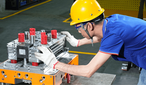
Motor molds are precision tooling used to produce core components of motors, such as stators, rotors, and end caps. Their precision and reliability directly determine the motor’s efficiency, noise level, and lifespan.We understand this crucial aspect and focus on overcoming the core manufacturing challenges of high precision, thin walls, deep slots, and stacking in motor mold production. We integrate automation concepts throughout the design and production process to ensure that we provide customers with high-performance, stable, and efficient mold solutions.
We can provide a comprehensive range of motor mold types, including: Servo Motor Mold,DC Motor Mold,AC Motor Mold,Plastic Edge-inserted Motor Mold,Plastic Encapsulated Conditioning Motor Mold,Winding Motor Mold,Motor Cover Mold,Motor End Cover Mold,Motor Bracket Mold,BMC(Bulk Molding Compound) Motor Stator Mold,BMC(Bulk Molding Compound) Motor Rotor Mold,Washing Machine Motor Mold,Air Conditioner Motor Mold,Refrigerator Motor Mold, etc.
Our Core Technical Advantages
We understand that every detail of motor molds is crucial to the final motor’s performance and lifespan. Therefore, we focus on four core technology areas, transforming our expertise into stable and reliable productivity and product competitiveness for you.
High-precision Lamination and Balancing Design
We ensure precise lamination dimensions and minimal burrs through advanced mold technology. Furthermore, through balance design technology, we guarantee the dynamic balance of the iron core during high-speed rotation from the source, directly improving motor energy efficiency and reducing operating noise and vibration.
Automated Insertion Integration Solution
We integrate these complex assembly processes, such as manually embedding insulating paper, magnets, or bearings, into the mold. Through a precision mechanism, we achieve automatic and accurate embedding of inserts during stamping or forming, significantly improving production efficiency and ensuring product consistency.
Special Surface Finishing and Long Life Design
Stamping silicon steel sheets causes severe wear on the molds. We select top-grade wear-resistant materials and apply special surface treatment technologies such as coatings to form a protective layer on critical parts of the mold. This increases the mold's lifespan several times, directly reducing downtime for mold changes and lowering production costs.
Full-process Simulation Verification
Before the mold steel is put into processing, we complete a "virtual trial production" on the computer. We use simulation technology to simulate the electromagnetic performance, temperature rise, and deformation of the motor under real working conditions. We optimize the product during the design phase to ensure that the parts produced by the mold achieve optimal electromagnetic performance and mechanical strength.
Our Core Technical Advantages
We understand that every detail of motor molds is crucial to the final motor’s performance and lifespan. Therefore, we focus on four core technology areas, transforming our expertise into stable and reliable productivity and product competitiveness for you.
High-precision Lamination and Balancing Design
We ensure precise lamination dimensions and minimal burrs through advanced mold technology. Furthermore, through balance design technology, we guarantee the dynamic balance of the iron core during high-speed rotation from the source, directly improving motor energy efficiency and reducing operating noise and vibration.
Automated Insertion Integration Solution
We integrate these complex assembly processes, such as manually embedding insulating paper, magnets, or bearings, into the mold. Through a precision mechanism, we achieve automatic and accurate embedding of inserts during stamping or forming, significantly improving production efficiency and ensuring product consistency.
Special Surface Finishing and Long Life Design
Stamping silicon steel sheets causes severe wear on the molds. We select top-grade wear-resistant materials and apply special surface treatment technologies such as coatings to form a protective layer on critical parts of the mold. This increases the mold's lifespan several times, directly reducing downtime for mold changes and lowering production costs.
Full-process Simulation Verification
Before the mold steel is put into processing, we will complete "virtual trial production" on the computer. Simulation technology is used to simulate the electromagnetic performance, temperature rise, and deformation of the motor under actual working conditions. Optimization is carried out during the design phase to ensure that the produced parts achieve optimal performance.
How To Parnter With Us To Develop Your Motor Molds
The superior performance of an electric motor begins with the precision manufacturing of its molds. We treat the creation of each mold as a rigorous systems engineering project. This is our core process from understanding requirements to delivering the finished product, ensuring that what we deliver to you is not just a mold, but a reliable commitment to quality.
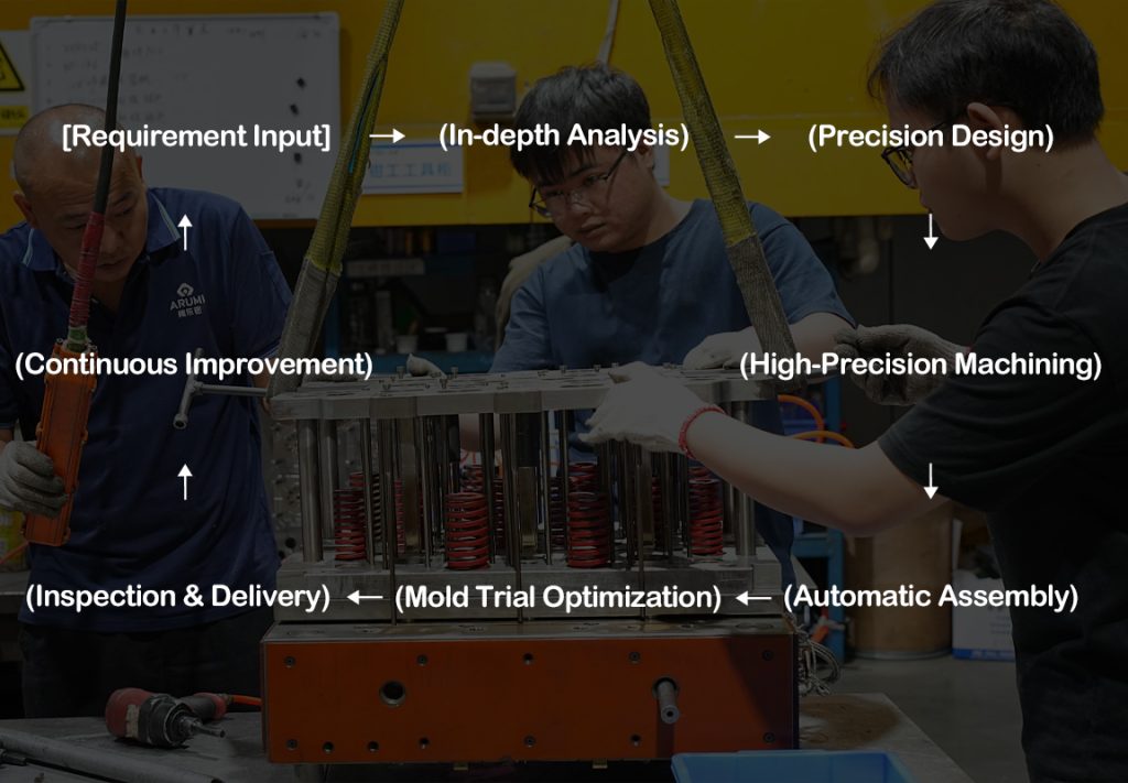
01.In-depth Analysis
Input your drawings and requirements for a technical feasibility assessment
02.Precision Design
Complete digital design including simulation verification and output machining instructions
03.High-Precision Machining
Utilize equipment such as wire EDM to transform the design into precision parts
04.Automated Assembly
Assemble and integrate automated units to complete the mold body
05.Trial Production and Optimization
Conduct trial production, adjust to optimal conditions, and produce qualified samples
06.Inspection and Delivery
Perform comprehensive inspection on the samples; deliver the complete set upon passing inspection.
07.Continuous Improvement
The end point of the process is also the starting point for improvement; experience is fed back to future program
Our Quality Control Standards
Factors affecting the quality of motor molds typically include maintenance cycle and cost, dimensional stability, surface roughness, material utilization, demolding, and auxiliary production cycles. We have established a rigorous control system from the design stage to after-sales support to ensure that every mold you receive is reliable and receives professional support throughout its entire lifespan.
Precision Control Standards
We understand that the precision of motor molds directly determines the performance and efficiency of the motor. Therefore, from the core precision of individual parts, assembly and motion precision to comprehensive testing of the final assembly, our internal standards far exceed industry-standard requirements.
Lamination Gap Control
- Our Standards: ≤0.005mm
- Reduce eddy current losses and improve motor efficiency by 2-3%
Coaxiality Tolerance
- Our Standards:≤0.02mm
- Reduce vibration and noise by 30% and extend bearing life
Groove Positioning Accuracy
- Our Standards:±0.003mm
- Optimize magnetic flux density to reduce torque ripple by 15%
Surface Roughness
- Our Standards:Ra 0.2μm
- Reduce the resistance of stacked iron cores and improve production efficiency
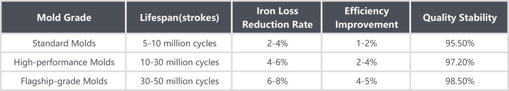
Mold Life and ROI Quantification
Extending mold lifespan not only significantly reduces unit production costs but also improves overall production line efficiency by minimizing downtime and maintenance frequency. More importantly, high-quality, long-life molds ensure product consistency and stability, which is crucial for meeting stringent quality standards and customer requirements.
|
Mold Grade
|
Lifespan(strokes)
|
Iron Loss Reduction Rate
|
Efficiency Improvement
|
Quality Stability
|
|---|---|---|---|---|
|
Standard Molds
|
5-10 million cycles
|
2-4%
|
1-2%
|
95.5%
|
|
High-performance Molds
|
10-30 million cycles
|
4-6%
|
2-4%
|
97.2%
|
|
Flagship-grade Molds
|
30-50 million cycles
|
6-8%
|
4-5%
|
98.5%
|
Unit Cost Optimization
- For every additional 10 million strokes, the cost per unit decreases by 22%
- Mold amortization cost comparison: Flagship-level molds are 35-45% lower than the standard
Improved Production Efficiency
- Advanced mold maintenance intervals increased by 40%, reducing unplanned downtime
- Mold changeover time decreased by 30%, improving overall equipment efficiency (OEE)
Energy Efficiency Gain Conversio
- A 3-8% reduction in iron losses directly translates into savings in motor operating costs
- Magnetic circuit optimization results in a 2-5% efficiency improvement
Quality Stability Assurance
- Assembly errors reduced by 40%, performance loss decreased
- First-piece yield increased by 8-10 percentage points
- Product consistency is maintained throughout the entire mold lifecycle
Our Quality Control Standards
Factors affecting the quality of motor molds typically include maintenance cycle and cost, dimensional stability, surface roughness, material utilization, demolding, and auxiliary production cycles. We have established a rigorous control system from the design stage to after-sales support to ensure that every mold you receive is reliable and receives professional support throughout its entire lifespan.
Precision Control Standards
We understand that the precision of motor molds directly determines the performance and efficiency of the motor. Therefore, from the core precision of individual parts, assembly and motion precision to comprehensive testing of the final assembly, our internal standards far exceed industry-standard requirements.
Lamination Gap Control
- Our Standards: ≤0.005mm
- Reduce eddy current losses and improve motor efficiency by 2-3%
Coaxiality Tolerance
- Our Standards:≤0.02mm
- Reduce vibration and noise by 30% and extend bearing life
Groove Positioning Accuracy
- Our Standards:±0.003mm
- Optimize magnetic flux density to reduce torque ripple by 15%
Surface Roughness
- Our Standards:Ra 0.2μm
- Reduce the resistance of stacked iron cores and improve production efficiency
Mold Life and ROI Quantification
Extending mold lifespan not only significantly reduces unit production costs but also improves overall production line efficiency by minimizing downtime and maintenance frequency. More importantly, high-quality, long-life molds ensure product consistency and stability, which is crucial for meeting stringent quality standards and customer requirements.
Unit Cost Optimization
- For every additional 10 million strokes, the cost per unit decreases by 22%
- Mold amortization cost comparison: Flagship-level molds are 35-45% lower than the standard
Improved Production Efficiency
- Advanced mold maintenance intervals increased by 40%, reducing unplanned downtime
- Mold changeover time decreased by 30%, improving overall equipment efficiency
Energy Efficiency Gain Conversio
- 3-8% reduction in iron losses directly translates into savings in motor operating costs
- Magnetic circuit optimization results in a 2-5% efficiency improvement
Quality Stability Assurance
- Assembly errors reduced by 40%, performance loss decreased
- First-piece yield increased by 8-10 percentage points
- Product consistency is maintained throughout the entire mold lifecycle
Some Successful Application Cases
Different motor applications place vastly different demands on molds. From high-speed new energy vehicles to long-running industrial equipment, and even precision, quiet home appliances, our mold technology is deeply embedded in the manufacturing of core components across various industries. No matter your field, you’ll find a customized solution at Wontech.
Air Conditioner DC Motor Stator
By optimizing the mold material and structural design, we have solved the wear and precision problems in the high-speed stamping process.
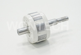
BMC Rotor Drive Motor
The challenges of shrinkage fluctuation and dynamic balance in BMC materials were addressed, achieving dimensional stability of ±0.03 mm and reducing noise.
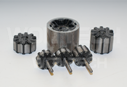
PBT Rotor Drive Motor
Specialty PBT engineering plastics and precision insert molding technology have solved three core problems of micro drive motors under high-speed operation: dimensional stability, insulation failure, and weight bottleneck.
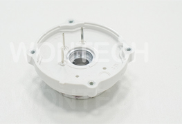
Motor End Cap
By designing a hot runner system and employing micro-venting technology, the problems of insufficient filling and air marks of BMC material in complex heat dissipation structures were solved.
FAQ

“What are the core factors determining the final cost of motor molds?”
The core factor is the comprehensive technical complexity. Besides steel, the real cost drivers are:
1. Design complexity (e.g., multi-station progressive machining, automated insert integration)
2. Materials technology (using powder metallurgy high-speed steel or cemented carbide can be several times more expensive than ordinary steel)
3. Precision level (for every micrometer-level improvement in tolerance, processing and inspection costs increase exponentially)
4. Lifespan standard (the design, material, and process investment required for a commitment of 100 million strokes is vastly different from that for 50 million strokes).
Therefore, purchasing molds is essentially a critical investment in the performance, efficiency, and long-term production costs of the final product, rather than simply comparing prices.
“How to improve motor energy efficiency from a die-cutting perspective?”
The molds directly determines the geometric accuracy and material condition of the iron core.
Through high-precision blanking, the burrs on silicon steel sheets can be controlled below 0.01mm, significantly reducing eddy current losses caused by burrs.
Through optimized riveting design, the core stacking coefficient can be increased to over 98.5%, effectively reducing air gap reluctance in the magnetic circuit.
We have previously helped a customer reduce the iron loss of a permanent magnet motor by approximately 12% by optimizing the blanking clearance and cross-sectional quality of the stator slot die, directly improving the overall energy efficiency of the motor.
"What are the fundamental differences between servo motor core molds and ordinary household appliance motor molds?"
The core difference between servo motor core molds and ordinary household appliance motor molds lies in their performance and precision orientation.
Servo motors prioritize extreme dynamic response and positioning accuracy. Therefore, their molds must ensure extremely low cogging torque in the core and high symmetry in the magnet slots. Slot dimensions and indexing accuracy typically need to be controlled within ±0.002mm, and a special unloading structure is required to prevent deformation of the silicon steel sheet.
In contrast, household appliance motor molds prioritize stability and cost-effectiveness in large-scale production. Manufacturing servo motor molds to the latter’s standards will directly lead to motor torque fluctuations and increased noise, completely failing to meet the performance requirements of high-precision servo systems and affecting the overall reliability and lifespan of motion control.
“What are the main differences between motor molds and ordinary injection molds?”
Motor molds and ordinary injection molds differ fundamentally in design principles, precision requirements, and material selection. Motor molds primarily include stamping dies for the stator and rotor cores, rather than traditional injection molds.
The core differences are: motor stamping dies must handle the high-precision stacking of special electromagnetic materials such as silicon steel sheets, with tolerances typically controlled at ±0.005mm, far exceeding those of ordinary molds; the mold structure must consider electromagnetic performance optimization, such as the slot design directly affecting motor efficiency and noise; the working environment is more demanding, with high-speed stamping (typically 150-300 SPM) posing significant wear challenges.
Furthermore, motor molds need to integrate special functions such as automatic stacking and deburring systems to ensure a core stacking coefficient of over 95%. In terms of material selection, core components of motor molds often use powder metallurgy steel instead of ordinary mold steel to resist the continuous wear of the silicon steel sheets.
The testing and verification also differ; motor molds must undergo rigorous electromagnetic performance testing, not just dimensional inspection. This specialization requires a deep background in electrical engineering, rather than just mold manufacturing experience, to develop motor molds. This is also the core value of professional motor mold manufacturers.
“What are the key indicators and methods for precision inspection of motor molds?”
The core indicators for precision inspection of motor molds fall into three main categories: geometric accuracy, functional accuracy, and process stability. For geometric accuracy, the primary focus is on the stator/rotor slot dimensions. A coordinate measuring machine (CMM) is used to measure slot width, slot spacing, and concentricity, with an accuracy requirement of ±0.005mm. The flatness and perpendicularity of the stacked iron core are also crucial; a laser scanner can quickly acquire three-dimensional data.
Functional accuracy inspection is more complex, including magnetic performance verification: iron loss, magnetic flux density, and stacking factor are measured using a dedicated test bench. A high-quality mold should achieve a stacking factor of over 95%.
Dynamic balancing is critical for rotor molds; the imbalance must be controlled below 0.5 g·cm. Process stability is achieved through SPC (Statistical Process Control), with the critical dimension CPK value greater than 1.67.
In terms of inspection methods, we adopt a hierarchical strategy: first-piece full-size inspection (using a CMM and optical comparator); automated online inspection during production (sensors installed inside the mold monitor key points in real time); and periodic downtime depth inspection (once a week). For BMC motor components, additional electrical performance tests are required, such as withstand voltage testing (2500V/1min) and insulation resistance measurement (>100MΩ).
Furthermore, we establish a “mold file” to record data from each test, analyze it promptly, and predict future needs. While this comprehensive testing system increases upfront costs, it significantly reduces production risks for our customers.
“How long does the development cycle for motor molds typically take?”
The development cycle for motor molds varies depending on complexity. Standard motor stator molds typically take 8-10 weeks, high-precision BMC motor component molds take 10-12 weeks, while complex multi-station progressive dies can take as long as 14-16 weeks.
This timeline includes requirements analysis (1 week), 3D design (1.5-2 weeks), CAE simulation (3-5 days), machining and manufacturing (3-4 weeks), assembly and debugging (1-1.5 weeks), and trial molding verification (1-2 weeks).
Based on customer needs, we optimize the timeline through process reengineering and technological innovation.
“What parameters should be focused on during the trial molding stage of motor molds, and how to determine whether the mold is qualified?”
The primary concern is dimensional accuracy, especially stator slot width, slot spacing, and inner diameter. At least 20 consecutive samples should be inspected using high-precision measuring equipment (such as a coordinate measuring machine) to calculate the CPK value (≥1.67) and ensure dimensional stability.
The core stacking factor is a core indicator of motor performance. Through precise weighing and volume measurement, a qualified core stacking factor should reach 95% or higher. A factor below 92% indicates excessive burrs or insufficient flatness. Electromagnetic performance testing is crucial. Iron loss (W/kg) and magnetic induction intensity should be measured using a professional testing platform, with deviations from design values less than 5%. For permanent magnet motor rotors, the uniformity of magnetic flux distribution must also be tested.
Regarding surface quality, the stamped surface of silicon steel sheets should exhibit an ideal “bright band/fracture band” ratio (60:40). A 50x magnifying glass should be used to inspect burr height (≤0.005mm) and the quality of the stamped surface.
For BMC motor components, attention must be paid to air marks, exposed fiberglass, and shrinkage deformation, especially in areas with electrical clearances, which must be 100% defect-free. Process stability is verified through 8 consecutive hours of production testing, collecting data such as mold temperature, stamping pressure, and product weight. The fluctuation range should be less than ±3%.
To determine mold qualification, we use a scoring system: key performance (dimensions, electromagnetic characteristics) accounts for 60%, process stability for 25%, and ease of maintenance for 15%, with a total score exceeding 85 points.
Mold trials are not only an acceptance process but also an opportunity for optimization. We meticulously record every data point, creating a “mold file” to provide a benchmark for subsequent production.
FAQ
“What are the core factors determining the final cost of motor molds?”
The core factor is the comprehensive technical complexity. Besides steel, the real cost drivers are:
1. Design complexity (e.g., multi-station progressive machining, automated insert integration)
2. Materials technology (using powder metallurgy high-speed steel or cemented carbide can be several times more expensive than ordinary steel)
3. Precision level (for every micrometer-level improvement in tolerance, processing and inspection costs increase exponentially)
4. Lifespan standard (the design, material, and process investment required for a commitment of 100 million strokes is vastly different from that for 50 million strokes).
Therefore, purchasing molds is essentially a critical investment in the performance, efficiency, and long-term production costs of the final product, rather than simply comparing prices.
“How to improve motor energy efficiency from a die-cutting perspective?”
The molds directly determines the geometric accuracy and material condition of the iron core.
Through high-precision blanking, the burrs on silicon steel sheets can be controlled below 0.01mm, significantly reducing eddy current losses caused by burrs.
Through optimized riveting design, the core stacking coefficient can be increased to over 98.5%, effectively reducing air gap reluctance in the magnetic circuit.
We have previously helped a customer reduce the iron loss of a permanent magnet motor by approximately 12% by optimizing the blanking clearance and cross-sectional quality of the stator slot die, directly improving the overall energy efficiency of the motor.
"What are the fundamental differences between servo motor core molds and ordinary household appliance motor molds?"
The core difference between servo motor core molds and ordinary household appliance motor molds lies in their performance and precision orientation.
Servo motors prioritize extreme dynamic response and positioning accuracy. Therefore, their molds must ensure extremely low cogging torque in the core and high symmetry in the magnet slots. Slot dimensions and indexing accuracy typically need to be controlled within ±0.002mm, and a special unloading structure is required to prevent deformation of the silicon steel sheet.
In contrast, household appliance motor molds prioritize stability and cost-effectiveness in large-scale production. Manufacturing servo motor molds to the latter’s standards will directly lead to motor torque fluctuations and increased noise, completely failing to meet the performance requirements of high-precision servo systems and affecting the overall reliability and lifespan of motion control.
“What are the main differences between motor molds and ordinary injection molds?”
Motor molds and ordinary injection molds differ fundamentally in design principles, precision requirements, and material selection. Motor molds primarily include stamping dies for the stator and rotor cores, rather than traditional injection molds.
The core differences are: motor stamping dies must handle the high-precision stacking of special electromagnetic materials such as silicon steel sheets, with tolerances typically controlled at ±0.005mm, far exceeding those of ordinary molds; the mold structure must consider electromagnetic performance optimization, such as the slot design directly affecting motor efficiency and noise; the working environment is more demanding, with high-speed stamping (typically 150-300 SPM) posing significant wear challenges.
Furthermore, motor molds need to integrate special functions such as automatic stacking and deburring systems to ensure a core stacking coefficient of over 95%. In terms of material selection, core components of motor molds often use powder metallurgy steel instead of ordinary mold steel to resist the continuous wear of the silicon steel sheets.
The testing and verification also differ; motor molds must undergo rigorous electromagnetic performance testing, not just dimensional inspection. This specialization requires a deep background in electrical engineering, rather than just mold manufacturing experience, to develop motor molds. This is also the core value of professional motor mold manufacturers.
“What are the key indicators and methods for precision inspection of motor molds?”
The core indicators for precision inspection of motor molds fall into three main categories: geometric accuracy, functional accuracy, and process stability. For geometric accuracy, the primary focus is on the stator/rotor slot dimensions. A coordinate measuring machine (CMM) is used to measure slot width, slot spacing, and concentricity, with an accuracy requirement of ±0.005mm. The flatness and perpendicularity of the stacked iron core are also crucial; a laser scanner can quickly acquire three-dimensional data.
Functional accuracy inspection is more complex, including magnetic performance verification: iron loss, magnetic flux density, and stacking factor are measured using a dedicated test bench. A high-quality mold should achieve a stacking factor of over 95%.
Dynamic balancing is critical for rotor molds; the imbalance must be controlled below 0.5 g·cm. Process stability is achieved through SPC (Statistical Process Control), with the critical dimension CPK value greater than 1.67.
In terms of inspection methods, we adopt a hierarchical strategy: first-piece full-size inspection (using a CMM and optical comparator); automated online inspection during production (sensors installed inside the mold monitor key points in real time); and periodic downtime depth inspection (once a week). For BMC motor components, additional electrical performance tests are required, such as withstand voltage testing (2500V/1min) and insulation resistance measurement (>100MΩ).
Furthermore, we establish a “mold file” to record data from each test, analyze it promptly, and predict future needs. While this comprehensive testing system increases upfront costs, it significantly reduces production risks for our customers.
“How long does the development cycle for motor molds typically take?”
The development cycle for motor molds varies depending on complexity. Standard motor stator molds typically take 8-10 weeks, high-precision BMC motor component molds take 10-12 weeks, while complex multi-station progressive dies can take as long as 14-16 weeks.
This timeline includes requirements analysis (1 week), 3D design (1.5-2 weeks), CAE simulation (3-5 days), machining and manufacturing (3-4 weeks), assembly and debugging (1-1.5 weeks), and trial molding verification (1-2 weeks).
Based on customer needs, we optimize the timeline through process reengineering and technological innovation.
“What parameters should be focused on during the trial molding stage of motor molds, and how to determine whether the mold is qualified?”
The primary concern is dimensional accuracy, especially stator slot width, slot spacing, and inner diameter. At least 20 consecutive samples should be inspected using high-precision measuring equipment (such as a coordinate measuring machine) to calculate the CPK value (≥1.67) and ensure dimensional stability.
The core stacking factor is a core indicator of motor performance. Through precise weighing and volume measurement, a qualified core stacking factor should reach 95% or higher. A factor below 92% indicates excessive burrs or insufficient flatness. Electromagnetic performance testing is crucial. Iron loss (W/kg) and magnetic induction intensity should be measured using a professional testing platform, with deviations from design values less than 5%. For permanent magnet motor rotors, the uniformity of magnetic flux distribution must also be tested.
Regarding surface quality, the stamped surface of silicon steel sheets should exhibit an ideal “bright band/fracture band” ratio (60:40). A 50x magnifying glass should be used to inspect burr height (≤0.005mm) and the quality of the stamped surface.
For BMC motor components, attention must be paid to air marks, exposed fiberglass, and shrinkage deformation, especially in areas with electrical clearances, which must be 100% defect-free. Process stability is verified through 8 consecutive hours of production testing, collecting data such as mold temperature, stamping pressure, and product weight. The fluctuation range should be less than ±3%.
To determine mold qualification, we use a scoring system: key performance (dimensions, electromagnetic characteristics) accounts for 60%, process stability for 25%, and ease of maintenance for 15%, with a total score exceeding 85 points.
Mold trials are not only an acceptance process but also an opportunity for optimization. We meticulously record every data point, creating a “mold file” to provide a benchmark for subsequent production.
Partner with Us. Engineer Your Success.
- Get Your Motor Efficiency Analysis Report
- Download Motor Mold Guide
- Talk to a Molding Expert
- No.2, South Huatai East Road, Caosan PioneerPark,ZhongShan,Guangdong,China
- +86 13326981626
- ocean.h@wanglai.cn
CAPABILITIES


Copyright ©2025 Wontech | Powered by Wontech.All Rights Reserved.